Published in: Das Schwimmbad und sein Personal, edition 02/2019
... and many chefs on the mash of pool hydraulics.
*Quote Wikipedia: „In the Tichelmann system the pipes from the heat generator are fed to the heat consumer and back into the ring-laying so, that the sum of the lengths of flow line and return line wherein each radiator is approximately equal to. (…) The meaning is, that all radiators roughly equal pressure losses are exposed and thus same volume flows (…) adjust, even if no control valves are used. " We will come back later.
At the end of the pool hydraulics is the benchmark, whether the planning of a pool was successful. But who should adorn themselves with the success or must bear the responsibility for failure? What's "failure" in the pool planning? Where is the criterion to find? These are the questions we want to deal in this post.
Each of us has the mash "Beckenhydraulik" under the nose, But many of us, the mash does not taste, although he was very freshly cooked and all ingredients in line with the rules. Something has gone wrong with the many chefs, who stirred the pot.
Definition and targets
If we see the pool hydraulics as the movement of water in a swimming- or bathing pool, then this movement has two tasks. The movement is to transport contamination of the water to overflow channel and simultaneously distribute the disinfectant throughout the water volume.
For the removal of contaminants, there is probably no direct recognized test method. Of course you can simulate dirt, accompany, for example, floating wood chips during their ramble to the overflow gutter. But if the wood chips hike, either the pool hydraulics or the air speed over the water is responsible.
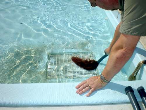
Photo 1: Hair trap test on floor drain, aqua&pools
As usual, if there is no criterion, one takes the experience to help. We learnt, the dirt on the pool floor can only be removed with a mobile vacuum cleaner. A fixed suction on the pool floor does not help.
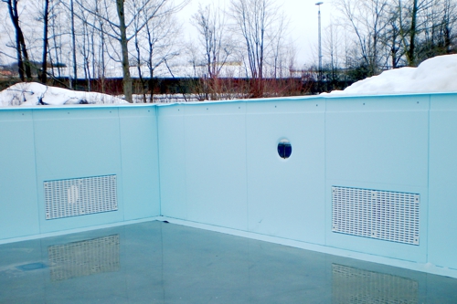
Photo 2: Wall suctions, aqua&pools
Also in the pool wall built suctions make more trouble than good. The risks, where our guests would be exposed through the openings, are confirmed by the deaths unfortunately, in many southern pools. The next good idea was the skimmer, sometimes called surface suction.
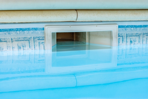
Photo 3: Wall Skimmer, fotolia.de
Due to its function, the upper layer of the water is always recorded. Apart from the width of the skimmer itself, the water level is still limited by the pool wall. If current or wind do not come to the rescue, remain the floating particles in a corner of the pool. Or, what is worse, the particles stick together with the pool wall and begin their microbial life. So even today, Italian companies seek their salvation in maximizing the skimmer width.
All this has led to the understanding, that the overflow channel should occupy as much as possible the entire circumference of a pool. In Germany, this finding is in DIN 19643, in Austria in the ÖNORM M 6216.
DIN 19643-1:2012-11, 9.2 Pool flow: "As a drain serves an all-round overflow channel."
How the water "in standardized operating condition" should leave the pool, we now know - or think it at least. Who still remembers the post to the overflow channel in issue 06/2015? Who does not, can online at aqua&pools the overflow channel search.
In the article we had proved, that a circumferential overflow channel only makes sense, when the flow is large enough for an encircling overflow of the water.
Channel length and flow
... are but in the calculation of the volume flow only in last place in a context. Nevertheless, we have to deal with these fundamentals us first.
This post is not to enumerate the many methods of calculation or compare, by the DIN or OENORM M 6216 offer. This should be treated in a later post. Free as in the old german video "Feuerzangenbowle" we face but still play the fool, and "What is a pool?“
A swimming pool is a hole (in the ground) with a piece of sheet metal (or other material) around. Somewhere the water come in and to the overflow come back out. Is nevertheless total easy, or?
As easy as it is not done to us by the authors of DIN. It starts with different categories and their containment, which help us with the naming of the pool.
After that each category gets a Formula forced,
which volume flow the pumps should now convey.
References to the overflow channel - None.
Evidence of the pressures - None.
So we make right now a moderately complicated example. A pool with dimensions of 50 x 25 meters. Aware of the category is not named here, but it could be a competition pool. Pity, according to DIN 19643 an unknown category!
FINA DSV difference
But even, if you have a "competition pool" wishes, you come into the conflict between the organizations. If you follow the rules of the German Swimming Federation, then the pool ranging from starting blocks must be deeper than 1,80 be. For pools, where competitions FINA be performed, can the pool be, however, 1,30 to 1,00 meters flat. Both caused not only different investments, both also attracts different operating costs by up. So you can already here start the first calculations. The cause of the demand for a different depth of water could be due to the German insurance rules GUV, which is to protect the amateur athletes from injury.
Water depth profile
A rectangular pool is an extremely greatly simplify the task. But even at different water depths it will be harder. So let's assume, the sample pool has an area with 4,50 Meter of water deph over 12,5 meters length. Then the pool floor should be up 2,10 meter rise, so that water polo can also be played in the shallow area. A research on the future types of use is so helpful before determining the water depth.
Water flow
For this pool so following volume flows are provided to us by the filter system. DIN 19643-1:2012-11 Table 3 - Nominal loads and flow rates says, Whether swimming- or diving pool, the treatment- Water flow (lower value) should be 0,222A / k.
With this formula, the volume flow is therefore 0,222 x 25m x 50m x k. What's "k"? The capacity factor k of the process combination is the permitted number of bathers per m3 treated water. DIN 19643-2:2012-11, the part for sand filter, says: For the calculation of the volume flow according to DIN 19643-1:2012-11, section 8 is when using this combination of processes a load factor of at most k = 0.5m-3 to use.
Therefore, probably the phrase "You half portion!“. So the 1m³ water comes half a person to the treated water.
According to this calculation the pool hydraulics are available 555m³/h. In the same table in a column of pools- Water flow (lower value) = 1,0 × La expelled.
Quotation DIN 19643-1:2012-11, 8.1 General: "For the dimensioning of the treatment plant, at least the hygienically justified treatment volume flow must be used. Results for the hydraulically-founded pool volume flow, a larger value, so at least this should be recognized as treaded processing flow. "
This we can rule out, 150m³/h of the circumference are clearly not greater than 555m³/h. But in conclusion it can be said, the pool gets maximum 555m³/h and a minimum of 150m³/h.
Of course, the wise operator knows, that everyone (saved) m³ reflected in the operating costs. What screw can be rotated? Yes, first the small inconspicuous "k" in the formula!
DIN 19643-4:2012-11, ie the part of ultrafiltration, says: „For the calculation of treaded processing volume flow according to DIN 19643-1:2012-11, section 8 is a loading factor of at most k = 1,0 m-3 to include. "
Even the flow rate has shrunk to 277,5m³/h. If we make the calculation on the proven visitors, can also rotate on the screw, as well as the target position of a part-load operation can be monitored inside and outside the pool operating time. The pool volume flow of 150 m³/h therefore seems quite mathematically in terms of operating costs represented.
The engineer, who gets involved in these rake games for the water treatment plant, probably already submitted to the following rule: DIN 19643-1:2012-11, 8.5 Calculations based on the rated load of the pool, 8.5.1 General: “(…) The functionality of a plant according to 8.5.2 must go through a function proof according to DGfdB R 65.04 be detected." The planner, the criteria and methods contained therein should be known.
The pitfall
... is, as so often the conflict of interests. If planning for pools and water treatment plant were commissioned separately, the yellow lamps for liability gap should already flashing times. The planner for the water treatment plant expects the particularly low flow rate of at an early stage, at which the hydraulics in the pool still have to work (and the operator seems to be happy).
That pool hydraulic do this in future, is then in the air, because of pool planner has been reading in the DIN, how to arrange the inflow openings. Maybe he also got the advice of the pool contractor (and its technical additional offer) belongs and the number of inflow openings reduced? But even an increase in the number may be wrong, as happened recently in Denmark.
Risks the example of the overflow edge
Of course, for the pool planner is NOT written in the DIN, that he should tell the structural engineer of the building as a precaution, that at the end of the construction period, the weight of the water must not deform the foundations or ceiling slabs. The static DIN leaves a setting and flexibility, the water level of the pool but NOT!
Perhaps the pool planner has indeed further said to the structural engineer, but the footing appraiser has not experienced it and accepted the limited, but too much flexibility of the ground? There are footings, that change at every filling and emptying each of the pool. Asks Sabine and Armin from the trade fair issue. Ok, we deviated, back to the other part of the pool hydraulics.
Basics of the nozzles
The nozzle for the inflow in the pool intended to produce a jet of water at a certain speed and direction. Possible lossfree of water flow is accelerated. Pressure energy is converted to velocity energy. The speed is necessary, so that the water jet can spread over distance.
There is thus a relationship between the pressure upstream of the nozzle, the speed in the nozzle and the propagation of the beam in the water. The propagation usually we call "throw wide" of the nozzle. In addition, the pressure- or energy loss in the nozzle is important.
Is responsible for the effect of the nozzle to the pool or the water treatment unit assigned? Who provides the characteristic of the nozzle with regard to the pressure loss and the throw distance?
Throw wide of the nozzle
So if the nozzle has the purpose, to generate the water jet with optimum length, then you have to know this optimal length first. Let us look again at the DIN.
Quotation DIN 19643-1:2012-11, 9.2 Pool hydraulics: “(…) In horizontal pool hydraulics the inflow openings have to be arranged offset to the respective longitudinal sides of the pool. " So that the necessary throw each nozzle is equal to the pool width. In our example, 25 Meters would this a pressure of 0,5 bar correspond.
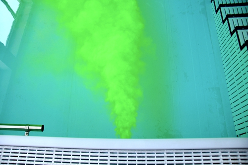
Photo 4: Horizontal nozzle with Uranine Yellow, aqua&pools
For comparison, now the inflow nozzles on the pool floor: Quotation DIN 19643-1:2012-11, 9.2 Pool hydraulics: “(…) For vertical pool hydraulics the number and distribution of the inflow devices must be selected, that for each about 8m2 the pool floor area, or about a circular area with a diameter of 3.2m or a square with side length of 2.8m, one inflow device is available. At a ribbon-shaped inflow area is covered by 1,6m to each side." Since "ribbon-shaped inflow" is not defined, we focus first on the value 8m². It creates a square grid between the nozzles with 2.8 m distance. The nozzles have a plurality of openings, therefore, the throw wide of the water jet of one of these openings must extend in the worst case to the diagonally adjacent nozzle. These are 3.96m. That would correspond to about 0.2 bar in our example.
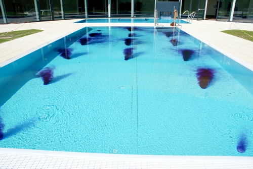
Photo 5: Inflow holes on the pool floor, aqua&pools
Do not scare, the photo is a small provocation. Also this nozzle could 0,2 bar pre-pressure have, but still does not throw wide. What happened? Simple answer: There is no nozzle, but a bottom opening.
Vectorization
Well, the designer for upper pool has "forgotten" the purpose of a nozzle. The nozzle should speed up the water in one direction. Of course, the disinfectant can be distributed in a different way, but that is not safe, especially in indoor pools.
It is therefore important, to give the waterjet a direction. Wikipedia used to describe "nozzle" the word "tubular". In other words, the ratio of length to diameter of the nozzle should be as large as possible. We do not need to discuss more deeply terms such as diffuser and confuser and their forms here. These terms exist!
For calming, a bottom nozzle can also work that way:
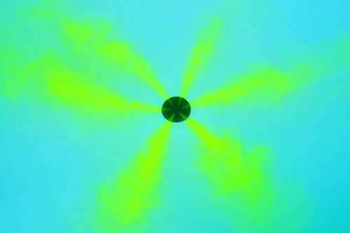
Photo 6: Floor nozzle with Uranine Yellow, aqua&pools
Noticed? The preceding numbers make 0,3 bar difference between vertical and horizontal system. This difference has an impact on the selection of pumps and their driving power. The special design of the component "nozzle" may increase or decrease this difference.
The correlation flow rate and pressure of the circulating pump
Anyone who read the article on the dimensioning of the pumps in Issue 04/2016 remember, knows the relationship between flow rate and pressure of the pump. Who does not, can online at aqua&pools look for the articles on the circulation pumps.
At that time written: So, what to do, to this value (pressure drop in the pipeline) to calculate? It seeks the path of the water between the raw water storage and swimming pool, wherein the maximum resistance is to be expected. (…) Thereafter, all the components and pipe sections are detected in this way and all resistors summed. To the pool include the nozzles!
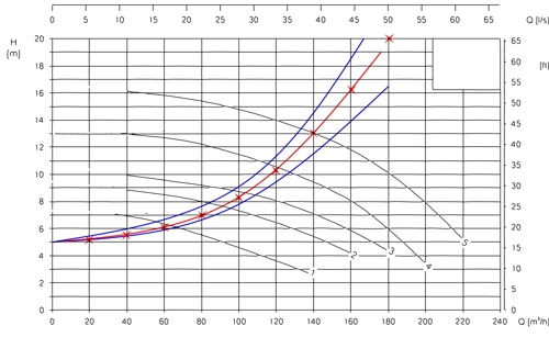
Sketch 1: Diagram pumps and pipe characteristics, Newspaper 04/2016
Piping and nozzles therefore generate a common resistor. This resistance is dynamically dependent on the flow speed and forms the pipeline characteristic of the system. The pump operates at the intersection between Pipeline- and pump characteristic. When the nozzle is replaced by a hole in the pool wall, the pump can not build up pressure, even if some of the pool manufacturers would wish. In addition, by leaving the characteristic curve, there is a big risk of destroying the pump. No back pressure is too high flow rates. The resulting high speeds of the water in the lower pressure region of the pump can generate gas bubbles, bubbles implode again on the pressure side, and thereby damage the pump impeller (technical term: cavitation) as this ship's propeller:
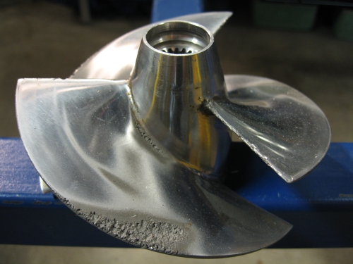
Photo 7: Cavitation on propeller, Source: Wikipedia, CC BY-SA 2.5, Axda0002, Eric Axdal
What does this have to do with the Tichelmann system?
Given the provocative title, we must now interpret the DIN again. Quotation DIN 19643-1:2012-11, 9.2 Pool hydraulics: “(…) By design measures, which observe the hydraulic interaction between supply lines and inflow openings, is to ensure that the distribution of pure water is as even as possible."
Translation: The same volume flow should escape at each nozzle. The structural measures are intended to ensure this. Please, what measures? Here, the Tichelmann system comes into play. We adapt the text from the first paragraph of our understanding: In the Tichelmann system, the pipes of the circulation pump until any inflow nozzle routed so, that the sum of the pressure losses is equal to. (…) The meaning is, that at all nozzles about the same pressure is present and thus the same volume flows (…) adjust, even if no control valves are used.
A brief comment on the control valves. Some logic can not be reversed just. Anyone who tries, a horizontal system with 8 manual ball valves to adjust, who understood neither the word "control valve" nor the complexity of the task. I know competition pools with horizontal system, because the manufacturer has the resources for 15 Ball valves DN50 and 4 dyeing experiments wasted, before the difference between "Try" and "Calculation" was clear enough.
But what does such a supply system look like? We start with the vertical system, the following figure shows the example pool from above.
The vertical system
... is in DIN 19643 described as follows. For safety, we repeat:
DIN 19643-1:2012-11, 9.2 Pool hydraulics: „(…) For vertical pool hydraulics the number and distribution of the inflow devices must be selected, that for each about 8m2 the pool-Surface, or about a circular area with a diameter of 3.2m or a square with side length of 2.8m, one inflow device is available."We start first with the 2.8 m intervals, that is easier. We must 2 nozzle connecting at this distance:
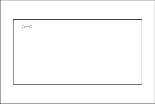
Sketch 2: Tichelmann-System with 2 jets, aqua&pools
If you want 2,8m comply with the grid, then be it in the next step 4 jets. The system of the same pipe lengths and equal pressure loss is to be met, then it must go on absolutely symmetrical now:
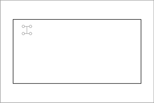
Sketch 3: Tichelmann-System with 4 jets, aqua&pools
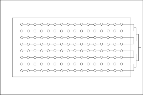
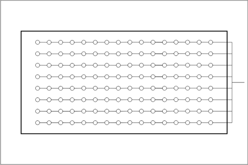
In this system, it continues with 16 jets:
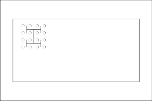
Sketch 4: Tichelmann-System with 16 jets, aqua&pools
The symmetry of forces now in 64 jets:
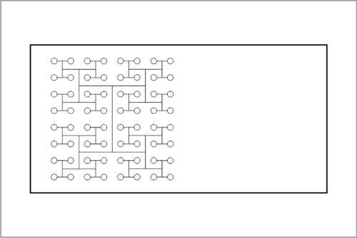
Sketch 5: Tichelmann-System with 64 jets, aqua&pools
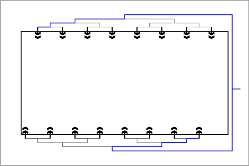
A step is, of course,. The total input 128 jets are now distributed symmetrically. The two blue lines are the same length, the number of tees is equal. Of course, the main pipe must be correspondingly tapered. These reductions must be installed symmetrically. But the goal seems to be reached.
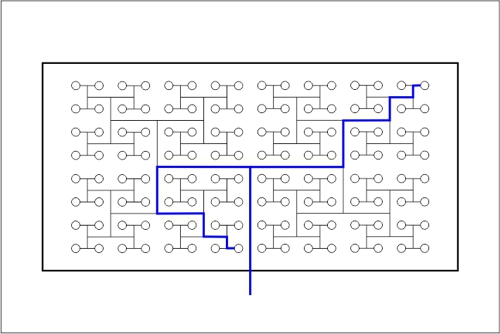
Sketch 6: Tichelmann-System with 128 jets, aqua&pools
In this system, the pressure loss is largely generated by seven tees. Of course you can influence the pressure loss with a generous dimensioning. In addition to the significant cost for many fittings and the huge pipe lengths should consider the pressure loss in this distribution compared with other systems. Often misappropriating, that the pressure loss need about 0,4bar more of the circulating pump.
The big door in the DIN
If you look closer, then you recognize, that the edge spacing of the outer nozzle to the pelvic wall does not fit. An additional series but would destroy the whole beautiful symmetry. So let's re-calculate: Water 1250m² / 8m² each jet, these are at least 156 jets. If we were in Austria, there would be the first laws conflict with only 128 jets. There are 8m² per nozzle (in the swimming pool) fixed. The DIN leaves us a gap, which can be the salvation of our example.
DIN 19643-1:2012-11, 9.2 Pool hydraulics: „(…) For vertical pool hydraulics the number and distribution of the inflow devices must be selected, that for (…) or about a circular area with a diameter of 3.2 m (…) one inflow device is available. (…) Unrecognized, contiguous areas can not exceed 4m² (…) be." This raises the question, how large the gap is between 4 circles with a diameter of 3.2 m.
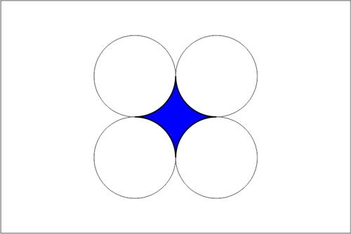
Sketch 7: Unrecognized, contiguous area, aqua&pools
For recalculation: the blue gap is

In our case, the unrecognized, contiguous area ie a maximum 2,197m².. The path to greater distance is therefore open! The distance between the nozzles can thus be selected evenly length/16 or width/8 to 3.125m. The rules of DIN remain nevertheless fulfilled. The necessary pressure at the nozzle is raised by only 0.01 bar, not worth mentioning.
There are of course not many pools, where this symmetrical piping is not possible. What can you do there? Differ from Tichelmann System? This is possible, you can even avoid the dreaded calculation. Anyone who read the article on the dimensioning of the pumps in Issue 04/2016 remember, perhaps remember, that the pressure loss in the tubes is always dependent on the velocity of the water. The reversal is:
The lower the speed of the water, the lower the pressure drop. For low speeds is therefore only the cross section must increase.
Arrangement of the nozzles as inflow channel
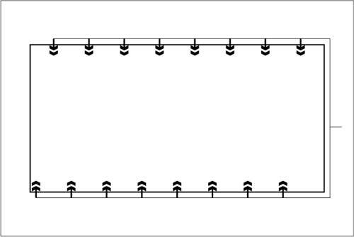
So probably was the inflow channel, which can be found in almost every pool made of stainless steel, invented.
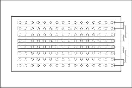
Sketch 8: Inflow channels with Tichelmann distribution, aqua&pools
These and all other drawings are drawn on the distance 2.80m. In our example with 555m³/h only 69,375m³/h flow on a single channel. A common channel cross-section of 30x30cm leads to an initial speed of 0,214m/s. The pressure loss in the inflow channel can be neglected.
Instead of the 7 tees in pipework of the individual nozzles, the pressure loss is based on the arrangement of inflow channels plus Tichelmann connector on only 3 tees. In our example, 3/7, So about 0,17bar.
Where there is light, there is also shadow.
If one assumes a continuous cross section for the inflow channel, which in reality hardly a manufacturer should do, then the water is slower in the channel after each nozzle. If one establishes the relationship to the distance of the nozzles, one knows the time, it takes the water from the channel-start to the channel-end.
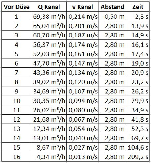
Table 1: Calculation of times for disinfectants, aqua&pools
Between the moment, where the disinfectant to nozzle number 1 exit, and the moment at which the disinfectant to nozzle number 16 arrives, pass over 11 minutes. Whether this is an advantage- or a disadvantage is, we will evaluate later in this article.
Presumably, the use of an inflow channel system is in some projects a structural engineering disadvantage. The space for the inflow channel is always accompanied by an increased space requirement of the pool. The statically necessary dimensions of the bearing plate change adversely. Alone, if it is necessary to go deeper for foundations, take this into account in the cost. Since the inflow channel is used as a supply of inflow nozzles by almost all manufacturers of stainless steel pools, at this point we do not want to miss the advantages. The stainless steel inflow channel is a part of the thin-walled sealing of the pool. So that the requirements of the account for "watertight concret" (in German "Weiße Wanne") to the constructive concrete. Such a channel can be opened and clean by the way.
The hydraulic calculation as an alternative
... presupposes nozzles, which are adjustable. In the horizontal system that is the common practice, relatively unknown to bottom jets yet. My former Italian client wanted to face in Reichenbach the competition for a large outdoor swimming pool , in which the vertical system was anchored in the tender. The architect Mr. Hofmann had, very clever, paired the inflow systemto the pool by tender . www.architekten-wh.de. Suitable nozzles were not available within the company, so at that time I had to "develop" new nozzles. In the first step, the goal looks like:
Sketch 9: Piping in line with Tichelmann distribution, aqua&pools
If one continue the table for the water speed until the pressure is calculated at each jet, so one can calculate the cross-section of the jet holes.
The nozzle close to the supply then the smallest cross section and the nozzle at the end of the line has the largest cross-section. Since the piping is unlikely to change after the completion, the nozzles were "made-to-measure" after estimation of the economic efficiency instead of the "adjustability" to implement.
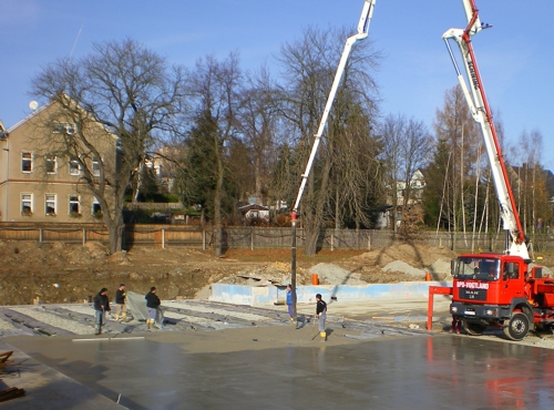
Photo 8: Reichenbach sports pool concrete, aqua&pools
If one is able to calculate and produce the finished nozzle,, what sense then makes the connection of the pure water by Tichelmann System? Nothing! One must nevertheless take only the pressure losses of fittings and pipelines of the distribution in the calculation of the nozzles. The further reduction of the pressure loss is enough reason for the calculation work.
The piping in Reichenbach was at that time of the WTA Plauen GmbH realized. Although some employees WTA doubted the calculation initially, the uniform jet image on the entire 50 meters, it has been before (successful) Dyeing experiment convinced.
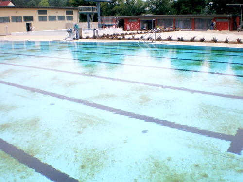
Photo 9: Reichenbach nozzles picture in the sports pool, aqua&pools
It continues unsymmetrically
By calculating the nozzle, it is possible, to build an asymmetrical distribution. This looks schematically like this:
Sketch 10: Calculated piping in line, aqua&pools
The practitioner will immediately notice, that the tees and angles with 90 degree are drawn. Of course, the calculation creates the possibility, the cheaper hydraulically 45 degree fittings to use or not to place the main connection in the center. Because instead of a channel now the pipelines are of sufficient size in our example with DA160, the time between the first and the last nozzle drops to below 3 minutes.
Free forms
Unlike with an extensive calculation, it is probably not possible, to provide free-formed pool at each nozzle with the same volume flow. The Tichelmann system would fail here. But who always builds sports pool?! No matter, how many nozzles are to be supplied in the same direction, the calculation can take into account all. we stay with the example object Reichenbach. There, for example, the adventure pool poses far greater challenges.
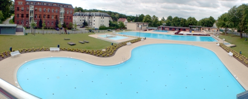
Photo 10: Reichenbach, View from the slide, aqua&pools
The absolutely chaotic piping of the adventure pool from the only accessible side was compensated here with the inflow nozzles.
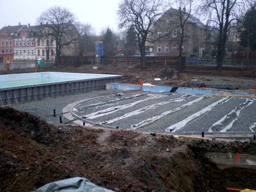
Photo 11: Reichenbach adventure pool, piping, aqua&pools
The nozzle image in dirty pool shows , that the calculation even in free form pool (successful) is possible.
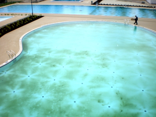
Photo 12: Reichenbach experience Basin jet image, aqua&pools
From the vertical to the horizontal
Also for the horizontal flow are the DIN 19643 Hints. DIN 19643-1:2012-11, 9.2 Pool hydraulics: „In horizontal pool hydraulics the inflow openings have to be arranged offset to the respective longitudinal sides of the pool. The distance between the inflow openings in the pool wall may not exceed one-third of the pool width. The inflow openings should be approximately in the middle between water surface and pool floor, in diving pools in two levels, to be arranged. The lower level should be about 50 cm above the pool floor. In order to achieve a sufficient mixing of the pure water in the pool water, the minimum pressure must be provided at the inlet openings. This is calculated from the pool width according to equation (11): p= 0,02b. Where p is the minimum pressure at the inflow port, in bar, and b is the pool width in m."
When reacting this paragraph literally, the pool hydraulic CAN work, BUT DOES NOT HAVE TO. Therefore, you should ask at the latest after this note an experienced specialist planner. It's like so often in life, only the knowledge of the rule says nothing about its application.
A vote for the special planners
Let's not fool ourselves, who does not know the pitfall, has no fear, to use the road. Coupled with the above-described responsibility gap is this, what looks easy, an unpredictable fiasco. The stupid thing is, that the error is only apparently in a staining test. A few examples of failed horizontal dyeing experiments are at aqua&pools to find at the familiar web address.
Who believes now, it follows here the addition or correction of the DIN quote, was wrong. First, it would only lead to more chaos and, secondly, one could therefore believe, not needing the special planner.
So we bear in mind, that the horizontal flow of a pool require different dimensions of the throwing range. Was it the vertical system 0.2 bar, then the width of a 25m competition pool are responsible for 0,5bar. Here, the horizontal system is much more sensitive to too low pressure. In vertical system, the dead zones are recognized only somewhat time-delayed, whereas the horizontal flow of a nozzle provides much larger areas. Is a horizontal nozzle miscalculated, there is no compensation from the other nozzles. The following diagram shows the uniform supply of the nozzles (with DIN assembly) with the Tichelmann system. Of course, once again required in the, because symmetric, number of each side eight nozzles.
Sketch 11: Horizontal system with Tichelmann system, aqua&pools
These are many superfluous pipelines. Of course, we can now also make the intermediate step of an oversized distribution, but we better come immediately to the usual pipework mode.
Sketch 12: Horizontal system with calculated nozzles, aqua&pools
Too often, the calculation of the nozzles is already been replaced by the installation of throttle valves. Combine the number of nozzles with the cost of the instrument and can then imagine the futility of reconstruction.
Advantages, which may arise by the calculation.
Of course, the possibility, to calculate the nozzle, the premise of this system of piping. And again you can take advantage of this opportunity for more properties. In DIN is written: „The inflow openings should (…) be arranged in diving pool in two levels. "
How about combi pools with different water depths? Should the volume flow be divided proportionally to the water surface or proportional to the number of nozzles? Should the lower nozzle row get more volumetric flow than the upper nozzle series? One can calculate all this.
If a competition pool will be built temporarily, then the horizontal system is mainly used. At 1.80m depth of water with one or two horizontal rows of nozzles. The outer lines remain unused in width 25m, so that the same conditions prevail for all swimmers. Nevertheless, athletes complain on the lines 2 and 9 (and rightly), to have been pushed by the strong flow of the nozzle or at least obstructed. With a calculation one can reduce the upper nozzle row and distribute the majority of the volume flow over the lower nozzle row. If a pool has critical areas, you can "attribute" this area a higher volume flow.
Admittedly: until now it was a very one-sided view, because free-form pools have at least at first glance, a tendency to soil inflow. At second glance, you can see, that the skillful utilization of the attraction and the distribution of wall nozzles allow horizontal inflow. But for this we must first consider the different structure of the nozzle.
Meaningful hydraulics of the individual nozzle
As different as the throw-lengths are also the tasks of the nozzles for the wall- or for the floor. The floor nozzle is to distribute the flow as effectively as possible in all directions. Contrary to the term "vertical inflow", however, the nozzle should swirl the water volume as completely as possible with a high horizontal proportion. One could believe, the flow of water upward should be greater than the fall velocity of the dirt. Achieving this is almost impossible and requires a much larger volume flow. Thus, the effect of a floor nozzle should look no circumstances as in the provocative photo 5: Inflow holes on the pool floor, aqua&pools:
In the next photo of the horizontal component is larger, and therefore, where the desired effect.
Photo 13: Floor jets dyeing attempt Eriochrome black, aqua&pools
One can almost say, in the photo is one vertical nozzle, but it is a group of small nozzles at the bottom horizontal incorporated.
Especially when a wall-jet in horizontal "Strahlenturbulenz-System" will be used, is not the distribution, but the focus of the beam wanted. Finally, the beam should be able to reach the opposite wall. But in addition, it should not interfere with the oncoming beam and distracted. In this nozzle, therefore, in addition to the calculation of the correct free cross-section, the formation of the beam by means of confuser and diffuser becomes important. Even the construction of the nozzle cover can cause bunching or turbulence of the beam and thus contribute to the success.
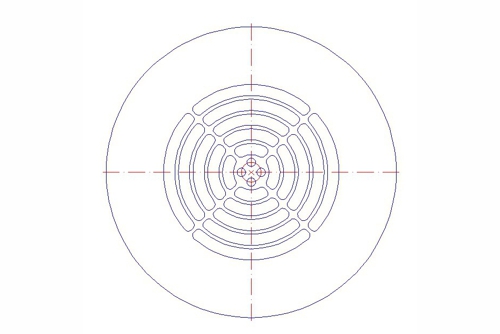
Sketch 13: Nozzle cover wall, aqua&pools
For the cover, of course, the safety provisions of the EN apply 13451. Nevertheless, the free area must be kept as large as possible.
Oblique thought
At the same time you can define about the entire construction, at what angle, relative to the wall, the beam is to be formed. It does not always make sense, to work orthogonal. It is supposed to happen, that the poll floor is slanted and the beam is inadvertently diverted into the deeper regions of the combined pool. With simple means you can counter it.
Simulation
As everywhere in our environment, there is an app for all this. The app you can buy, but including the training of the operator, the app is certainly more expensive than the entire pool. I also know a company, what has gone on this path as a pool manufacturer. The calculation of one nozzle was 5 years with the software possible, the calculation of 2 mutually influencing nozzles failed due to computer computing power. A simulation of the flow of a complex system including overflow channel is probably still unthinkable today.
Well, there are service providers for All, who have to use their capacities. So if you prefer simulation instead of knowledge and experience (of its special planner) want to invest, can contact me like.
But why all this?
Because in the end, the success is checked! Let's see in the information sheet of the German Society for Bathing, R 65.04-2011, 4.3 Effectiveness of pool hydraulics: „For evaluation, transport- and mixing operations should be observed and documented by adding a dye to the filtrate in the pool. (…) The coloring of the entire pool water volume must visually within a maximum of 15 minutes be recognizable. " Short, the work of the person responsible is controlled at the end. The information sheet R 65.04 the rear end of the causal chain, which brings the planners of the pool in the duty, to prove its calculation of the pool hydraulics in a dyeing test.
Causal chain
First, we naturally want to extend the causal chain. About the information sheet is DIN 19643. The quote DIN 19643-1:2012-11, 9.2 Pool hydraulics: “For checking the effectiveness of pool hydraulics is the DGfdB R 65.04 directed." Sounds somehow after a recommendation.
But who wants to turn even a little on the screw to reduce the flow rate, gets in the paragraph 8.2.2 Minimum overflow and pool volume flow to feel full hardness: “The functionality of a plant according to 8.5.2 must go through a function proof according to DGfdB R 65.04 be detected."That sounds quite different.
Also, the Federal Environment Agency has in the recommendation Hygiene requirements for pools and their monitoring in 2013 fixed: „After start-up, after a reasonable time, a functional test in accordance with directive 65.04 "Functional testing of systems for the treatment of swimming- pool water in accordance with DIN 19643: 1997 - 04" is recommended. The final acceptance after the award- and construction contract procedures (VOB) is not a substitute for this function test. This should not be in the contract scope of the company, which is responsible for the construction of the plant, but made directly by instructing the client (Builders task).”
Higher is at least the Infection Protection Act. We do not have to repeat the therm for the water of a swimming pool here. It is more practical, on a couple of details to DIN EN 15288-2, Swimming pools - Part 2: Safety requirements for operation; German version EN 15288-2:2008 enter into. Let's take Appendix A (normative) Dye test — Operational regulations once before.
Inaccuracies and clarifications
Place A.2 "To avoid adsorption, the water treatment plant must be bridged during the test components, which use the filter media, which may impair the dye (for example, activated carbon, Hydro-Anthrazit). The plant is to configure, to the lowered water column reconcile." What this means? Components with activated carbon are usually the filters. A short circuit on the closed sand filters can be produced with the fittings, but the preparation for circuit and pump throttling is maybe not available for free. Under certain circumstances, one has a problem with the gravity (vakuum) filters, which do not have to contain this circuit from home.
Place A.6 "The progressive change in color should be checked and recorded by photographing or video recording. The timing of the first insertion of the pigmented water in the tank until a uniform color is to be measured." In the section on the inflow channels we came upon this question. Here marks "from the first introduction" so the first nozzle as the start of timekeeping. The time until the last nozzle of the channel thus will be lost. But this section has it otherwise in itself. "uniform color" is a much greater demand than just "thecoloration of the entire pool water volume".
Deinking test
Of a deinking test in the other documents was no talk yet, the DIN EN 15288-2 brings it into our discussion. Yes, the Austrian OENORM M 6216 has implemented this "second part" long time, he is not rocket science. Instead of the color - chlorine is dosed, which dissolves the color again. The deinking trial is still much more demanding than the staining test. A small clear spot on the pool floor is difficult to see through colored water. But a color cloud in the same place can be seen very well with clear water. Where is it written? On Place A.9: “At the same position is a chlorine amount of about 5 mg/l pool water according to the same criteria as the Eriochrome black T into the water to bring.”
Here it becomes expensive for indoor pools! The dimensioning of the maximum metering capacity of chlorine is believed to DIN 19643-1:2012-11 been made. In point 11.2.1.3 Testing of chlorine dosage is described: “After complete mixing, and at least 20 s flow time, for example, in a measuring water pipe, must be at the highest concentration of free chlorine in the pure water: a) at indoor swimming pools: 2mg/I; b) in outdoor swimming pools: 10mg/I." That means, during the planning of the water treatment plant, either a 2.5-fold over-dimensioning or an additional system should be installed for the one-time inspection.
Error coupling
May be something more? Even if one keeps everything, you can as usual falling into the traps. In A.3 is spelled correctly: “The chlorine value is to 0 lower, for example, by the addition of thiosulfate." Takes the motivated employee TO MUCH thiosulfate, then the chlorine is quickly lowered to 0,00mg/l. But what about the excess thiosulfate, which is still and permanently in the water? You can feel it in the deinking test. Then the law of the jungle applies: Thiosulfate eats chlorine, not chlorine eats color!
Reduced volume flow
Initially, we had an impression of the possibilities of reducing the volume flow. But we must be clear: if we turn to one of these screws, what to do in terms of operating costs in any case, then one is forced at least into the R 65.04 became. Don't overlook, that you have to meet the dyeing test with the REDUCED flow.
Summary
We have fought our way out of the hydraulic systems on their optimization up to their proofing. All without claiming to be complete and without really writing the costs behind it. We want to leave this to the concept of the planner, finally, he gets paid for it. As an all-important criterion, the dyeing- and deinking test and presented the possible obligation to carry it out. Now there is only one question left: How can all this be integrated into the planning of my future swimming pool?
Recommendation
At the beginning of each idea for new buildings or for the renovation of a pool is a municipality or an investor. Does the municipality follow the procurement rules, then she will probably call a competition for architects. This is where it usually crystallizes, which pool system the architect prefers. Unfortunately, however, play the operational costs, which result from individual design elements, rarely a role. The client should therefore already be sensitive to the costs of operating.
It's certainly not harmful either, already in competition a variant comparison of at least the pool design and the pool hydraulics plus with invest- and operating-cost estimate.
Architects are often animated by the competition, instead of conveying the real "beau-beautiful" costs. Two things can help: 1. To announce, that the calculation is technically reviewed and considered in the assessment, and 2. The (fair) check for commissioning to be defined accurately at an early stage.
Let's assume, the prerequisites described above have been created, what to do then? It must the following informations be discussed, are bundled and fixed by contract.
- Minimum and maximum flow of the pool,
- Accuracy of the overflow edge of the pool,
- Dimension, number and position of the drain support the gutter,
- Hydraulic system with arrangement of the nozzles and position as well as dimension of the transfer point,
- Required pressure at the interface between water treatment plant and pool hydraulics with minimal volume flow,
- Volume flow of the staining test,
- Basis and implementation of the staining test and
- Flexibility of the results.
Finally, a discussion and food for thought to the last point of the list. If the special planner is charged the full risk, then he takes no risk. However, the flexibility could also look like this:
It goes to the theoretical minimum everywhere and sets the practical minimum only after the first practical check. Only then does the dyeing- and the deinking test for me a sense!
Outlook
From the first to the current article we have followed in the series the way the water from the pool through the water treatment plant. Already in this way, we had to touch on topics from the construction of the pool. All topics are a prerequisite, to deal with the possible construction of a swimming pool too. This should also be the subject of the next article. Who wants to share his experience, who is like invited with small and large field reports.
Thank you for the interest! I am glad about every feedback.
 Loading...
The download of the printed version for registered users is possible here.
[wpdm_package id=’3991′]
Leave a Reply
You must be logged in to post a comment.