

Published in: Das Schwimmbad und sein Personal, edition 04/2016
… or how to find the right circulation pump?
A good friend recently asked me this and complained, that various sales consultants of the major pump manufacturers could not help him. A seller fails then usually, if the customer does not know what he wants. Now I know this friend for many years and have experienced, that one have to have something of a soothsayer, befor his thoughts (dimensioning) guessable. Maybe I just can not only help him with this post.
Well, there are now a number of websites, to facilitate the selection of a pump - and do this! It works, if you know, what information does the website need. That's why I want to start this post with the steps, which you should DO BEFORE talking to the pump salesman or calling a webpage of the favored manufacturer.
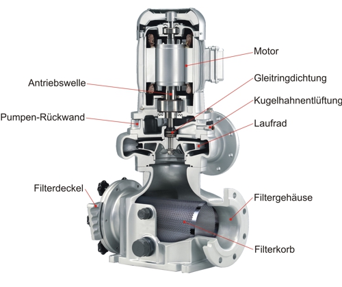
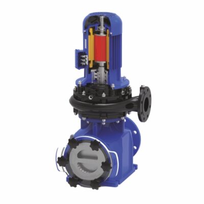
Illustration 1: essential structure of a circulation pump, Source: Herborner Pumpentechnik GmbH & Co KG
Why?
Apart from the recent aquaparks, which are traversed by a stream or even river, all others are equipped with a more or less modern water treatment plant. Would like some „Boat, bucket and spade" view as treatment, in DIN 19643 are found in every version the step "filtering". Here at last is clear, you have to pump water. The pool hydraulics too, so we may call it that, required drive power. Although this energy comes from water, but something has to this energy so placed in the water.
Now you may wonder, where does remain many kWh, that consume the circulating pumps. Physically speaking power = work, the product of force and displacement. spoken hydraulically is Energy = work, the product of pressure and volume mined. If I had written Flow, then we would jump from working on power. we want to have collected volume, what but also the calculation factor pressure? Are you able to keep the pressure small?
So back to work: If the pump with open valves in the circuit pumps, what they do so in some (or all) pools, then where is this pressure, which the pump generates? The solution is literally: "Pressure generated counterpressure!“.
Why do we stir us up early the tea in the cup around and this slows down his movements? Why the faucet in the morning splashing when opening and thereafter at a leisurely trickle? Water, which moving, Consumes energy through its internal friction! The particles rub against each other, warm up there and consume energy. The faster the movement, the greater the losses! Because this energy (as described above) composed of pressure and volume - and the volume almost can not change in the water - only the pressure remains, can suffer this loss. Therefore, you probably call it pressure loss and no loss of energy?
As so often, our forefathers could not also agree on a uniform definition. Not even when pressure! So if you read something of an "energy level" or "energy line", then there is usually meant the static pressure. The web page or a sales specialist of trust is so ask first: "Which volume flow, and what pressure should the pump provide for?" But what is meant is, which back pressure to overcome the pump. But how do you get the?
estimation or calculation?
If one is not able, to calculate the back pressure in the system, then deceives only an estimate about this little deception away. To acknowledge the round values, which are then listed in the "planning". For safety, of course, much too high, Waste energy so no one notices!
Let us begin with the laborious practice. Which hydraulic resistances must overcome the pump? As would be the geodetic pressure, caused by the difference in height of the water level of raw water tank and pool. This is the greatest, if the water level is at the raw water tank at its minimum. And here we are already at the first value, which is not static - it changes depending on the volume flow. Anyone who has read the article about the raw water tank, he can understand these values and take. The larger the volume flow in the circuit is - the greater is the pressure to be overcome.
At this point, my statement is visually nor thanks to the water level displayed. But this statement, that the resistance changes depending on the volume flow, applies to all other components as well. Each piece of pipe, each fitting, each instrument increasing its resistance with a rise speed water.
So, what to do, to calculate this value? You look for the path of the water between the raw water storage and swimming pool, wherein the maximum resistance is to be expected. So the way on most taps and the most distant and dirty filter to the most distant inlet nozzle. Thereafter, all the components and pipe sections are detected in this way and all resistors summed. Sounds simple, it is too! One only has to do it. For all elements of the pipeline, no matter how long or short.
Naturally arises before this thought the question, how fast the water is allowed to flow because in the pipeline? Only with a rough answer may be dimensioned pipelines and fittings. In most companies, the dogma does exist "not
faster than 2.5m/s ". This has the background, that the flow in the tube is not to be turbulent, because the internal friction in the turbulent regime increases extremely. Scientific justification is probably, that the Reynolds number of the water is less 2040 should be. For recalculation:

- v: Speed,
- the: Hydraulic diameter,
- V: Kinematic viscosity of the water.
The Reynolds number plays a role in all the other elements, so I would rather not be calculated on the scrap paper but in a table. If the dimensioning in the laminar region (<2040) is, then the next number lambda λ can be relatively simple (following Blasius) be calculated.

Maybe now some self-proclaimed scientists are sounding the alarm and explain this formula too easy. Yes, it is possible to complicated this, but we want here results. Plain to see, the Reynolds number is re-used because of the different speeds for each element of the calculation. We can use this Lambda now the resistance (pressure drop) calculate for each piece of pipe and each fitting. The formula of Darcy-Weissbach is:

- Δpv: pressure drop (derived unit SI : Pa)
- ρ: Density (SI unit: kg/m3)
- u: average flow rate (SI unit: m/s)
- λ: Friction factor (dimensionless)
- l : Length of the pipeline (SI unit: m)
- the : Inner diameter of the pipe (SI unit: m)
- ζ: pressure loss coefficient (dimensionless)
No fear, that can (and have to) be divided. Thus, only the formula for each piece of pipe

- Ro: pipeline
applied. For each fitting, Bow and instrument is
- Fit: Fitting
applied. Depending on the type of fittings you need of course the resistance coefficient . This value can be taken from various tables in literature or the manufacturer of the fitting or you also looking for the formulas in the contents of lectures or textbooks.
Now only the filter remains, the pressure loss, we need to consider. It would be nice, of course,, if the manufacturer would provide a characteristic for filters and filter filling. But you can make do with the dogma of course: "Clean filter 3mWs, Filter rinsing at 5mWS!“.
The first interpretation is best observed the average, So the filter during operation with 4mWs. Please note, usually the front casing of the filter is not included in this value. So who in the front piping (dimensions) has reduced: Have fun with destroying energy! We dedicate ourselves to this topic in the next post.
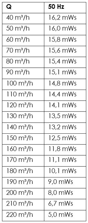
If you have all these values written together in a table, then one can form the sum of all the pressure losses in the pipeline and obtains the pressure, the pump will reach the volume flow. Happy will be, who has calculated in the table as the loss of pressure "y" completely from the volume flow as "x".
Let's assume, there are 140m³/h in 13,15 mWs (or 1,315bar)
If all of this is summarized in a table, then can easily change the volume flow and one obtains the pressure losses to a flow rate of 10, 20, 30, …. m³/h include. For multiple-user: In Excel using the scenario for. be from a point so 9, shown here in the diagram.
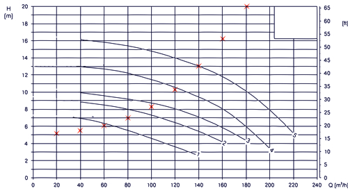
Diagram 1: Points in the Q-H diagram,
Graphic: aqua&pools
With the points you can not do much, in the following diagram, the dots are connected red.
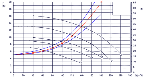
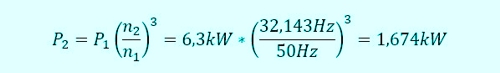
Diagram 2: Lines in the Q-H diagram,
Graphic: aqua&pools
The red line connecting the calculated points. The blue lines show the course when the filter (upper blue line) or freshly purged filters (lower blue line). The calculation process is, of course, remained the same.
Only now we can see the actual work, the selection of the pump, to start. It is now important, to have the data sheets of eligible pumps, to be able to comparison. Of course, for our example I have the manufacturer's instructions neutralized. It is always beneficial, to use and compare the characteristics of several manufacturers .
Step 1: Matching characteristic line
The data sheets are to search for pumps, whose characteristic line in point (140m³/h, 13,15mWs) cuts or near it comes. In our example, it is the characteristic line 5, in green below. This is now the moment, where my friend usually closes the lid of the notebook, and looks at the destination of his dreams.
But that the work is far from done. Even if I made a numbering of the steps here, it does not mean, that you do not even have to repeat steps too, in particular in order to achieve better results.
Step 2: Compare efficiencies
Transferring the intersection of the pipeline- and the pump curve in the graph of the efficiencies, then you should land on the "ridge" of efficiency. In the example, the manufacturer Eta = 83% expelled, which should be quite a good value. When incorporated several manufacturers in the selection, then of course the items need to be coordinated in the diagram. It is of little use, to compare the electrical efficiency of the first manufacturer with the coupling efficiency of the other manufacturer.
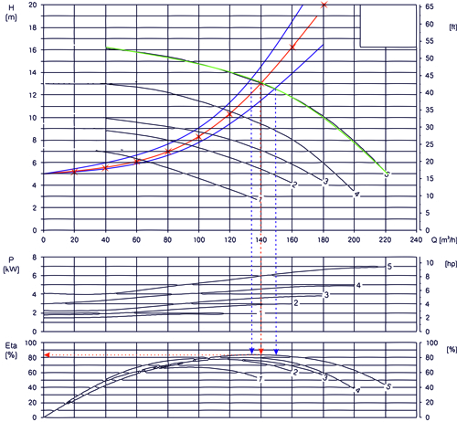
Diagram 3: Comparison of efficiency,
Graphic: aqua&pools
It is also important, where is the efficiency, if the filter move slowly from "clean" to "clogged". These are the two points of intersection (blue piping characteristics with green pump curve) also be transferred to the Efficiency. It is certainly to recognize, that no significant changes are present here.
The farther the pump is away from the optimal efficiency during operation, the greater the wear. In this case we are with the first operating point right, I could now call luck - or make the next step.
Step 4: Optimize dimensioning of the pipeline
In the calculation of the pipe dimensions, one generally starts from standard values for the flow velocity at first. We know from the calculation of the pressure loss, that this depends on the diameter of the individual elements. Now one should ask, what is the cost and bring a change of dimension. In the example, the characteristic of the pump would be at a lower pressure loss of 9mWs 4 to reach.
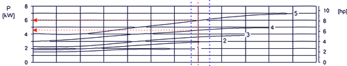
Diagram 4: Electrical power in the diagram,
Graphic: aqua&pools
Just as you have to ask, whether another hydraulic system with a lower energy requirement at the nozzle is possible. So it would be possible, 25% save the electrical load when you checked the cost of an increase in pipe size. To put it clearly: At this point the planning I play with dimensions, so that I either reach the next-low pump characteristic or reduce the material usage to the next-higher characteristic.
At an operating period of several years, in the indoor pool over the outdoor pool, results in a payback period, will gladly discuss any operator certainly. I myself have tried a few years ago, to move a well-known Italian pool manufacturers to optimize its inlet nozzles. The low interest in the operating costs of customers was exemplary negative.
Between note:
By the contamination of the filter, to this example the volume flow of 150 m³/h to 135m³/h will reduced. That will can always understand. But each equally aware, that therefore the electrical consumption of the pump is going BACK? From 6,3kW to 5.7 kW. I leave the evaluation of this relationship for the operation of the swimming pool every self. But in discussing with technical assistants do not forget the hygienic effect!
Step 5: Control the maximum pressure
The extension of the Green Line to 0m³/h ends around 17mWs. How to reach this point? Automatically, when intentionally or unintentionally, a flap is closed. It's so interesting, that all components could resist this pressure. The most sensitive element is probably the filter. If the selected pump curve too steep, then you should at least the risk of malfunction and destruction of the closed filter to be aware. An examination of the compressive strength in the documents is recommended at this point.
In order to leave no gap here ...
The gap in the characteristic smaller 40m³/h has no beauty reason but is very consciously drawn by the manufacturer. This area leads to a "improper operation" of the pump, in which damage can occur.
Nevertheless, you should contact the manufacturer, which maximum times are allowed in this area. Because textbook smooth acceleration of a centrifugal pump is usually: Starting against closed pressure flap. Why? Please take a look at the chart. The pump 5 only requires 3kW instead 6kW, the cabinet will be pleased!
If this process is to be automated with existing systems, please pay attention to the lowest possible speed when opening the flaps.
Similarly, of course, in the upper region, at pump 5 about 220m³/h. So if you want use this pump for mere pumping of water from the raw water tank, for example in the channel, it must "organize" at least 5mWs pressure loss so as not to destroy the pump.
Step 6: Control of additional operating points in flushing
It is supposed to happen, that is to take place with the same circulation pump, the backwashing of the filter. We please take it in this case to uncritically, and please ignore all the arguments for the rinsing with another pump / to other waters / talk about other tank. We take this operating point just from the first example. Is known, that the flow rate is set to double, less is known, that now is a completely different characteristic acts. The height difference between the water levels now lies between raw water tank and feed hopper in the filter. eliminates the flow resistance of the filter material, provided the air purge has been connected upstream. The changed settings can be found in the chart below 5 as brown pipeline characteristic.
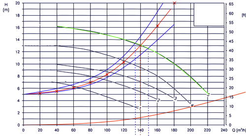
Diagram 5: Characteristic of the pipeline during the flushing,
Graphic: aqua&pools
In the diagram 5 can be seen, that pump 5 alone, could not reach that point outside the graph. The pump ends at 220m³/h, it lacks 60 m³/h Here, then, a new search for a pump would be required, which can reach both the operating point and the backwash. Certainly, the efficiency plays no significant role during flushing, but to destroy the pump may not cause such use.
An open problem (Pump can not!) without an indication of at least one solution is of course no way for this post. But the reader will forgive me this profane reconciliation!
Two pumps, when one is insufficient!
Of course, no one will provide a pump on reserve, only to have them once a week for 5 Minutes to flush to use. (Or does it?) But it is not unlikely, that he 2 or more filters with the same dimension, thus also more pumps of equal size, has in the system. Then the second pump from the other filter could be "borrow" for flushin, a correspondingly planned piping provided.
In pumps of the same characteristic, the common pump curve forms in parallel by "horizontal summation" of the volume flow.
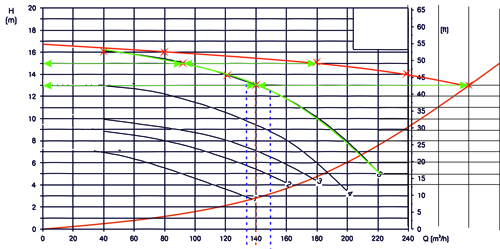
Diagram 6: Parallel connection of two equal pumps, Graphic: aqua&pools
Here the graphical solution to the problem. Horizontal green arrows are the same length and transfer the points horizontally to the right by doubling the distance, the red line is then the common characteristic of both pumps.
If you have ever sent its filter filling in the mud water tank? Thoughts can nobody guess, so honest, probably everyone! What was the issue? At the small inconspicuous change, you overlooked at brown curve (and forget) could. Because hydraulic does not depend on the wishes but according to the realities. On closer look you can see, that the line of flushing must be throttled by a valve so, that the operating point is reached at 13mWs. So if you want like to keep its activated carbon, do not forget the crucial throttle!
Step 7: Control additional operating points - reduced operation
So far we have only talked about the standard operation of the plant. But it is of course also about, the plant outside the opening time with 50% the volume flow to operate. OK, of course you can 1 from 2 pumps switch off, if you have planned two units. But the shutdown never reduces the flow but never to 50%, as pumps moves on the characteristic of the system. If you the example of chart 6 used (I had no desire to draw again), then you can point the operation of point 2 pumps (280m³/h at 13,15mWs) to the point with 1 Pump (208m³/h at 6,7mWs, brown line in the diagram 6). With this measure, the flow is on 74% lowered. To further reduce need to change the system characteristic so, that to achieve 140m³/h a pressure drop of at 13,15mWs .
This "restriction" but would not lead to further significant energy reductions, but only generate additional losses.
Conclusion, if you want to work exclusively with the shutdown of pumps, then at least a third division (3 parallel pumps in a circle) be sought.
Frequency converters, not a panacea but good!
With a frequency converter, the speed of the pump can be changed. Now asked me the already above-mentioned Friend, how one can calculate the reductions for. Of course you need (and therefore I have described in such detail at the beginning) the pressure losses in the pipes and aggregates or individual values.
Well, if you've built the calculation continuously in Excel, then you can assign a pressure loss any flow in the pipeline. For this example, the scenario gives the following values (now deliberately changed in the world of Excel charts):
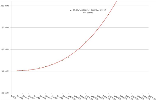
Diagram 7: Calculated points and pipe characteristic, Graphic: aqua&pools
Well, these values come yes from the calculation of the pressure loss. The work, be formed into a single formula, which outputting the each intermediate value, but seems "somewhat challenging" for every amateur mathematicians.
Perhaps it has anyone ever seen, me it is at least not yet succeeded, to move a manufacturer to transmit the formula for its characteristic. (Side note to all advertisers of the BDS (Union of German Pool-Masters)!) But, ok, you get it yourself. The table data is taken from the pump curve in the graph of the manufacturer and then translated the same Excel home remedies in a line.
For all, prefer to imagine that this figuratively, are the points on the graph 7 shown. The connection can determine Excel alone, there is a "trend line" third degree polynomial as. The automatically determined formula is also displayed in the diagram.
y = 1,543E-6x3+0,00019954x2-0,00259775x+5,1217
In direct comparison will notice, that the numbers from the chart differ. This is of course, because the numbers are also (a closer look) available on the non-graphical computing path of Excel. So you can top instead of the "x" in the formula to 50% volume flow 70m³ / h Insert, or access again directly to the table. The formula would look like this:
=TREND(Area Values pressure loss ; Range values flow ^{1.2.3};Flow ^{1.2.3})
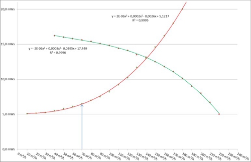
Diagram 8: Pipeline characteristic curve and pump performance curve 50Hz, Graphic: aqua&pools
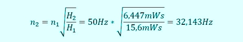
Result in both cases: The piping system has 6,447mWs pressure loss when the flow rate to 70m³ / h is halved. The question arises, which speed has to drive the pump, so that the curve intersects the point. There is a simple relationship between pressure loss, this time as a height H in mWs (Meters of water column) called, and speed of the pump, this time as a mains frequency n in Hz denotes.

This formula can be determined by changing the speed.
Of course, this can also be done for the points on the graph and of course this also results in another (blueness) line:
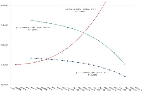
Diagram 9: Pump curve in 32,143Hz,
Graphic: aqua&pools
And to what end? Surely, to know, what power, now P in kW, this pump requires at this operating point. And there are, fortunately, for a relation. This is:

Converted and provided with values, we receive:
With 26,6% Power, the frequency converter 73,4% post savings for themselves. But these are theoretical values, which may well differ from reality. Take only the slip of the asynchronous engine, which could change the result.
Step 8: Consider alternative drives
I would not like to go into it, that a rough surface in the pump may lead to increased losses. The pumps, from which we start here, are non-corrosive and is provided with a thick coating smoothing. Where this is not so - even further ways of improving the consumption have only little sense.
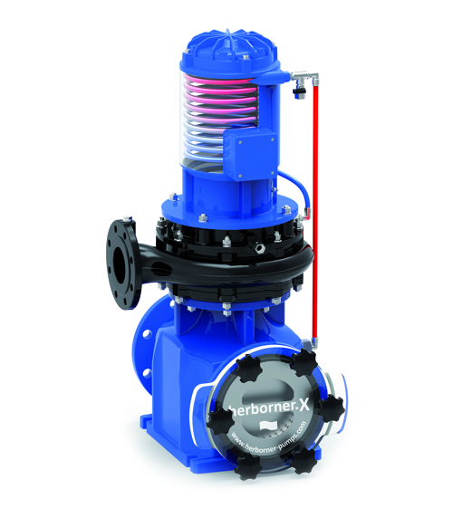
Illustration 2: Pump with heat exchanger engine,
Source: Herborner Pumpentechnik GmbH & Co KG
But now it's really an economic assessment made. In the first step, one could perform the heat losses from the engine by means of a cooling water directly to the water. This makes the unit robust. But what does it, if the exhaust air from the plant room is already "squeezed energy" from the air conditioning? It just brings discussions about efficiency - but no savings to the bottom line of the pool operation.
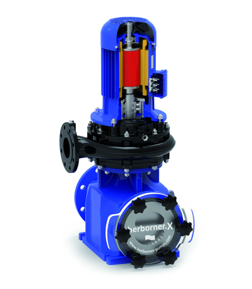
Illustration 3: Pump with permanent solenoid motor,
Source: Herborner Pumpentechnik GmbH & Co KG
The order of considerations is admittedly intended. At this point, perhaps significantly grown, that frequency converters seem the more effective way, make the best possible use of the pumps in a swimming pool. It could almost consider the frequency converters as "necessary". The same "opinion" are also the permanent magnet motors, because they need a frequency converter, at least for starting. But these PM engines have the advantage over the usual asynchronous motor, that they do not need a slip. This slips ensures losses, thus, the efficiency of the PM motor is better. Using data is therefore to calculate, how the investment for a PM engine pays off against the savings.
Step 9: Check the suction side
This suction side is a very special side. Often the test is simply ignored, all according to the principle "There will already resist!“. But in the pool are the so-called "pre-filter" usual, which can interfere with dirt quite clearly in the operating point of a plant. At the same time, more and more vacuum-sand filters are used, in which the filter resistor is arranged on the suction side of a pump. We bear in mind, what can happen:
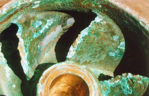
Illustration 4: Cavitation at the pump impeller
Now it is time, to bring the physics skills at school from behind the stove. Since there was even a Mr. Bernoulli ... Who remembers? "The sum of the static and dynamic pressure is constant!“ (or something like that).

- const.: constant
That means, where there are fast currents, where the speed is high, there, the dynamic pressure is high but the static pressure is low.

- stat.: static
That would not be so bad in itself, you would not have to operate with water in the water treatment. Water, which tends, to form steam.
Next step in the educative past: What is the boiling of water dependent? Correct, from ambient pressure. On the mountain, water boils at lower temperatures than at sea level. This is the static pressure, which this boiling temperature affects.
At point, that static pressure, which is eaten by the dynamic pressure, if motion comes into play. You sense it almost, Centrifugal pumps have to move. The impeller accelerates the water, This movement generates dynamic pressure, such as on top of a Airbus wing , that's why the static pressure reduced. And what luck, the pump therefore pumps! But if the static pressure is reduced too much, maybe only at some points of the impeller, then the water evaporates even at normal temperatures. This would not be difficult - if not the pressure would rise a few millimeters later strongly.
The newly born steam bubbles implode.
They tear it small particles from the surface of the impeller, unfortunately steadily. The impeller and other components have only a few chances!
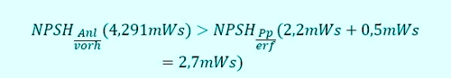
Of course, the manufacturers are trying hard, to keep the speeds small and uniform, but without a qualified use of the pump, even the best designers have no chance. Who has accepted, the computation would be to step 7 completed, sees now disappointed. It now applies even to consider, if
![]()
- Anl.: plant
- vorh.: existing
- Pp: Pump
- erf.: required
is. A reserve of 0,5mWs is supported by each manufacturer. NPSH? „Net Positiv Suction Head“, follow EN 12723 German also "NPSH". But who uses the know ...
The NPSH value of the pump's is on the chart 10 the intersection of the line to pump 5 with the known 140m³/h, who can read is as always at an advantage! But now even the NPSH value of the plant is missing.
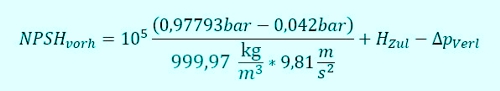
Should it be annoying, I hope it is at this point the last time: Who has calculated its pressure drops in tables - is also an advantage here. For the NPSH value of the system is none other than the pressure loss between the water level of the tank and the suction connection of the pump. Let's get to the formulas, first for the supply operation:

- G: Gas
- D: Steam
- Zul.: Intake
- Verl.: Loss
Here is present by the water level upstream of the pump, a positive pressure. Conversely in suction operation:

- S: Suction
Usually, the circulation pumps are below the water surface, so we want to focus on the supply operation. So we expect our virtual example. The location of the pump system was, let's say, Nürnberg. This city is located on 309m above sea level.
- pG: is the pressure, acting over the air to the water surface of the tank.
So first calculate this pressure. Who wants to search: It is the "international height formula".
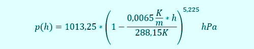
We use:
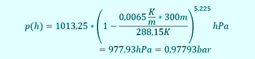
This value is plausible. Because with increasing altitude decreases the air pressure goes, starting from 1,01325bar at sea level, down. Now we need the vapor pressure of water in the tank. We are in the swimming pool, I put like 30°C to, Rather too much than too little. In the literature, a lot tables will find, I looked at the value
![]()
picked out. What is missing is the density

- W: Water
and the gravitational constant

so that we can use. The height difference between the water level and the pump nozzles depends on the type of use. Sucking from the raw water tank, so the amount has to be set at the minimum operating state. If parallel work of other pumps, the lower water level can in this volume (see article for raw water tank) be used.
If it is the pump for a vacuum filter, then of course the condition of the filtering must be applied. Here, then, is the maximum pressure loss of the filter material is to included in the characteristics of the pipeline. Apropos Filter, the pre-filter the pool water pump must not be forgotten. On one hand, it changes the position of the pump nozzle upwards, On the other hand, its pressure loss must (dirty) be considered.
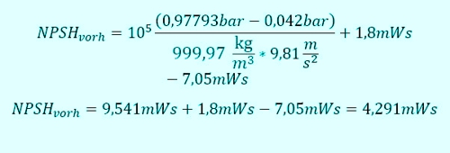
To adjust the level of difficulty the selected pump will therefore operate on a vacuum filter. The example is

The difference in height between water level and pump connections should be 1.8m. But add up the (flow depend) Pressure losses in the contaminated filter material (5mWs) and in the pipe on the suction side (2,05mWs).
In the diagram, it looks like this:
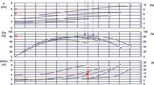
Diagram 10: NPSH-controls,
Graphic: aqua&pools
The condition:
- erf.: required
is fulfilled. The pump can be operated at this connection under these conditions.
Conclusion after 9 steps
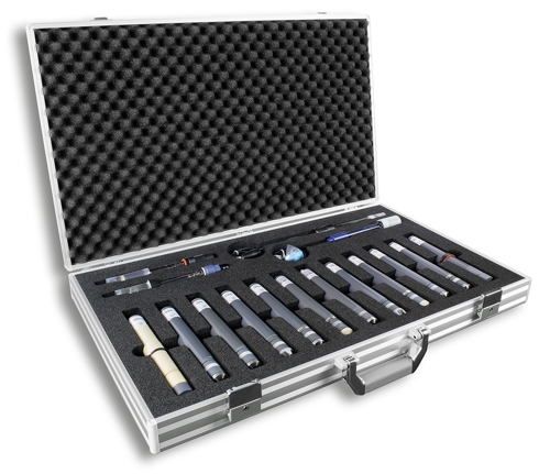
I believe, it has become clear, that the selection of a pump is not easy. There is experience, satisfying to start. But without accurate calculation of a pressure loss, it just does not work. No manufacturer can do the work for, although some engineers would like to see it that way. If the pump does not reach the performance or infinitely exceeds this does not reflect well on planning. Even the panacea "frequency" then fails as an argument. If the pump operates in the wrong area, then the cavitation is faster than the warranty end! Of these, quite apart, are the selection of the pump and the intended use (without cavitation) not the responsibility of a producer but the engineer. Who gets these benefits usually paid and the calculation should have handed over the documents. On that we have joy in our pumps, as this photo shows:
Because of the many different variations in the tubing, I offer this time no final table in Excel. Instead, the necessary formulas can be found in the text. Have fun imitating, for therefore this article is written. For information on Dirk.Sura@aquaandpools.de I'm grateful.
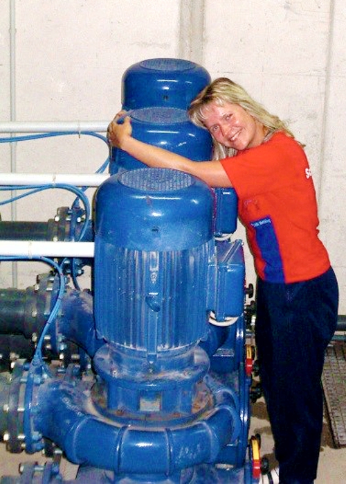
Photo: Bernburger Freizeit GmbH

Maybe this article can also be understood as an appeal to the client. These calculations are necessary BEFORE tender. The underlying assets must be calculated and are in the tender, so that each bidder can calculate and offer HIS suitable pump. With the tender "1 piece of water treatment with 140m³ / h" the costs of a previous planning are not saved but only postponed. The following errors are inevitable by "This was not so advertised!" and multiply the price. We should understand this relationship and support the planner as much as we can control it!
Here for members is in German language the original newspaper “Das Schwimmbad und sein Personal” the Association of German Pool Masters, edition 4 / 2016


Leave a Reply
You must be logged in to post a comment.