Published in: Das Schwimmbad und sein Personal, edition 06/2015
The angular has to go in the round ...
Here we go, Here is part two! After a few calls of our members, I would like to make clear again: It is in this series is not an explanation or even comment on the DIN 19643! To DIN much is written, in our Journal too. May remain near the mountain all their prophets and cite the commandments! No, I would rather arouse interest, what solutions there are in addition to the DIN, wait what pitfalls on the way to new or renovated swimming pool (can) and what the parties have to pay attention everything / should / can. Our members should KNOW what stuck in the grab bag "Planning my swimming pool". Not to be confused with CAN and DOING, this is usually the architects and engineers are paid. Finally, it is about the daily tool of the swimming champion.
Shame on me, one of the biggest challenges right now for the staff of each pool I have the last item under the (Write-) desktop let it folling down:
The channel grating!
Think the architects responsible for about the color scheme and the slip resistance by and think the engineers responsible about bar spacing and free cross-sections, so the staff has only one question: "How do we get the brown and green slime from this narrow channel grating???“.
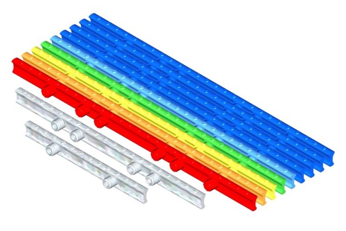
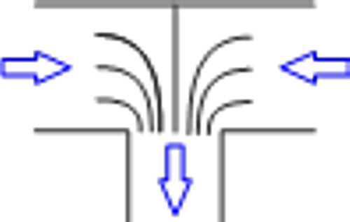
Graphic: aqua&pools, 2002
Less is more, as so often in life! The graphic above, I hope so, an example of minimization of the corners and edges. how looks a dirty channel grating, so I will here nobody nerves. But experience shows that it is just wrong, when two professional groups about the things to think, makes the third working hard. yet the channel grating the "dirty corner" each basin! Instead philosophies about to set up, whether the rod fits better into the concept longitudinally or transversely to the overflow edge, should trained eyes pay attention, whether the water flows instead of falling, and whether the channel grating has redundant corners and edges. Here's an example: The channel grating in the following photo is (positive) not tied to any radius and can be exposed in almost every curve. The (negative) Price for this are extremely many corners, Edges and even cavities.
So the overflow edge must be millimeter thus the volume flow (Q) sufficient, to the entire circumference (B) a small difference in height (h) to generate between the water level and the edge. As a check, one can calculate the volume flow, said ± 2 = 4 Millimeter = 0,004 Meters can overcome over a length of 1 meter channel. This is the formula of Poleni as follows:
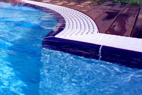
Photo: www.myrthapools.com
On the (Pool-) Rand looked ...
We, as so often find relief! No, a solution "clean obsolete" we do not find, but yet (I think) considerable relief. The plastics technology has made progress in recent years, which go far beyond the "lotus effect" of colors. If one could produce the same channel gratings with a material but, what does not taste the microorganisms. The solution to this was recently awarded an innovation prize.
The graphics of colorful channel gratings I drew for that time. Recently, grids can be made of a "antimikrobakteriellem" material at RZB Zeller Berlin GmbH, that prevents the biological growth. The plastic is directly changed so, that still can fly around a couple of releases electrons on its surface. Fatal to the digestion of microorganisms but irrelevant for water and man. Cleaning is easier for a bite. No, No metal ions will be dispersed in the water, as our southern neighbors only too happy to do.
I think, this message was an interruption of the planned sequence value. Maybe standing in some bathrooms investment decisions on, where this reference work can ease some the swimming pool. I ask for advice!
If we let it flow!
Is there a reason, think about this little "surge water line"? No later than, if you can convert these ideas into cash. Because of the surge of water transport in an overflow channel and a slope line is pure waste of money. For simplicity, we assume the pool from the last post and expect with the values of 25×10-meter swimming pool. The circulation capacity is 110m³/h and the scope = gutter length 70m.
When the water level of the surge water tank only 2 Meters below the water level of the pool is, then within each hour
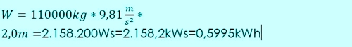
destroyed. First sounds not much, but on the other hand, we save a few watts LED lamps. Here not sound nearly 300W per meter height difference much? So it's worth, worrying about the piping.
In general, the surge water piping plays in the planning of a swimming pool (wrongly) a minor role. Because even in the planning of the building, the positions of the tanks are set. A hotel in Berlin has the pool in 5. upstairs, the ballance tank is in the basement. With a ceiling height of 3,50 Meters, the hotel operator must specially look forward power to the pumps via 5,8kW. Moscow is a pool in the 62. Floor of the Federation Tower, imagine this calculation before ...
But we start, as promised in the last article, with the channel processes. Even if the procedures usually a manufacturer other than pipes, sometimes even when the overflow channel, to have, they must cooperate with the tubes.
Which claims to the function of the surge water system we would write the planner to specifications, if we had the chance?
correctly dimensioned! Quiet! Efficient!
The calculations in the last post, we had determined the transport capacity of the spillway. But this capacity is abundant superfluous, if not at the end sits a channel drain, of this volume flow in the connected piping system brings. Channel and channel drain must be coordinated. Thus we are faced with the almost philosophical task:
The Board has in the Round!
Basically, we can probably assume, that it is in a channel drain to the transition from (square) Gutter in a (round) pipe is. The type of channel outlets is dependent on the design of the pool and around the pool. If here are load-bearing walls in the way, pulls tube against static principle "lose out". Although you have to pay the reinforced concrete or the hole in the wall only once, however, the hydraulic caused everyday costs! This is perhaps an indication to the architects and a look at the cost of value. The peripheral issues, is sealed in the structure, for example such as the channel outlet, or as the easiest to implement the channel outlet for the pelvic Bauer, we leave here for the time being to clarify the architect. The only important thing first, that the architect knows, that there still are tubes, the gap can not be calculated away.
Channel drain horizontally in the flow direction
This design is probably still quite rare, yet it is the most effective, and we can use it to build the considerations slowly. To size, we need the volume flow, to the channel transports the expiry and the height of the water level before the expiry.
In the last article, there were probably too many formulas, thanks again for the hints in this direction! We will limit the future to the most necessary.
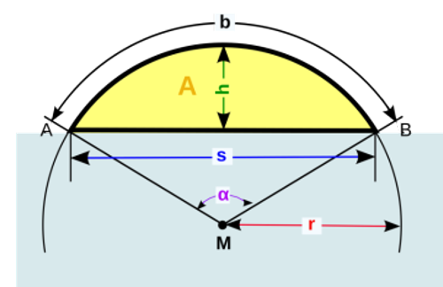
Source: http://commons.wikimedia.org/wiki/File:Circular_segment.svg
Continue: The subsequent tube has a circular cross section usually, the to 80% may be filled. With the role of these 80% we deal below, I ask for patience and acceptance. From the last article, we take as an example the following statement:
- The flow is 11 m³ / h or 0,00306 m³/s,
- The transition between rectangular and round gutter pipe is not 100 percent, Therefore, we choose an efficiency of μ = 0.75 and
- the speed of the water is before the expiration according to the old calculation 0,38 m/s.
This results in:
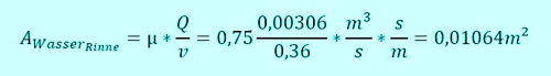
So it's a pipe select, that an area larger than at 0,01064m² 80% comprises filling.
The blue circle segment is calculated as follows:
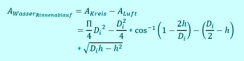
With the inside diameter
![]()
and the height of the water level above the trench bottom
![]()
becomes

This means, that the channel outlet of our example have a diameter of at least 126 must have mm, so that the water can drain. The transition must then be designed to, that the water level is seated in channel drain at or below to that in the trough. So a transition piece is necessary in any case. Of course you can calculate now go so far, that the ramp in the transition piece increases the speed, but we want to calculate only the necessary quantities.
Channel drain horizontally across the flow direction
Not only, that now the water flows in from two sides, So the flow is doubled. No, the water does not move freely in the channel drain. It does not flow in the direction, but transversely thereto,.
IF we could give to the water at the same speed, would now with the upper calculating a diameter of 178 mm for the channel drain required.
The manufacturers of the tanks arranged generally below the trough of a box, so that the flow channel can be applied laterally. When the water in the can "to racing each other", the energy is dissipated in the resulting turbulence.
Of course, the water eventually flows into the drain, finally, it is driven by the gradient in the pipeline and backwater in the drain box. The problem here: A free area for air exchange, So the upper rest 20% (yellow sector in the first sketch), does not persist and the gutter "noisy" before usually go.
Remedy can provide a simple device, that redirects the water towards the channel sequence. The baffles are spaced, which supplies the correct volume flow to the affected circle segment. Of course you can in terms of "The Square in the round," not simply transfer the same gap widths of the circular cross-section. With the above-calculated 178 mm thus resulting gap thickness according to the following table.
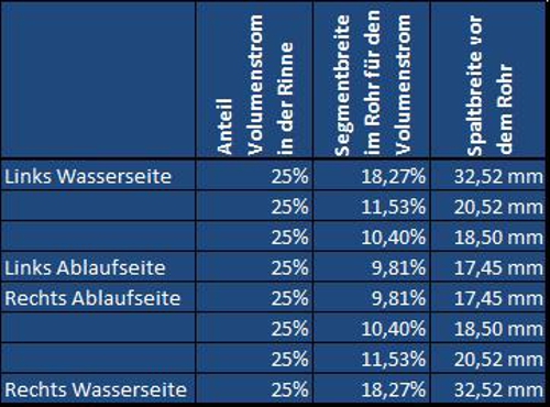
The percentages you can of course be transferred to any other diameter, provided that the 4-division retained.
Channel drain vertically
At this point we take some bonds supposedly foreign trades. The guild of plumbers and Spengler has been working for the 12. Century gutters of metals and their drainage. At that time, very few have in our part of the basics of the DIN 19643 employed. The plumber go in their literature, in my view rightly, assuming, that the flow channel is the bottleneck of the drainage.
In the area of roof drainage performance of a channel sequence with DIN EN 12056-3 Table 5 defined according to. The two right-hand columns are the complement to the ease of comparison with our calculated values.
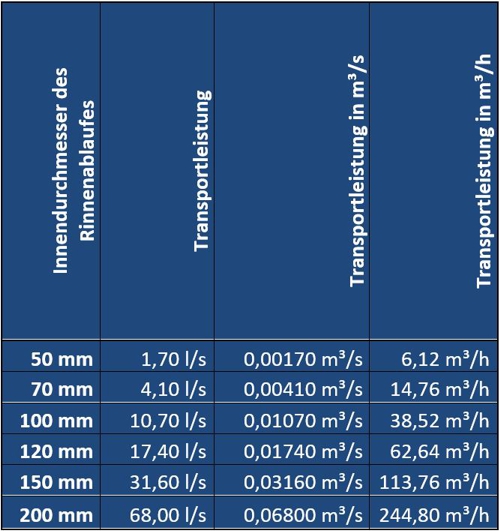
Table: Drainage capacity of gravity line in accordance with DIN EN 12056-3, Tab 5
Perhaps it was to remember, I am no friend of Tables. Therefore, there is also the formula for calculating itself to. Excel makes it possible. So who needs intermediate values or other values, I've got times already which prepared:
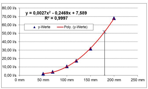
Diagram drainage capacity perpendicular
In the diagram, also developed by Excel quadratic formula is to. Who needs the functions in Excel, Please email to geschaeftsstelle@bds-ev.de. we stay in our example, then a channel drain is required, of the volume flow
![]()
controlled. In the last article I had discussed, why in my opinion in the outdoor pool, the factor 1,5 for the volume flow is not sufficient, also 2,0 would choose. So Consequently, we remain under pool conditions, with f = 2.0 to 44m³ / h or 12,22l / s due. The formula above gives us a minimum diameter of 105mm back, So we would have to use a vertical channel drain DN125 in the DN-series.
Whoever speculates on the KG-pipes and DN 110 has in mind, Please put in the brain memory and thinking at the end of the article on the effect of the seal!
www.ifb-deutschland.de/downloads.html/Cziesielski-Roeder-Dachentwaesserung.pdf
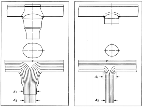
The DIN above 12056 expects, that the channel drain is not flanged directly into the gutter bottom, rather is formed as a feed hopper as shown in the sketch for roof drainage. The funnel covers the entire channel width.
we are fixing to this point, that it is probably cheaper, to invest in this funnel in place to plan shorter distances of processes.
When calculating the vertical channel outlets by this method but it must not be forgotten, that overflowing of the gutter is not the biggest problem with "outboard roof drainage". Please, one must not dogmatically follow such regulations, rather must also pay attention to the conditions, under which the rules have been created, on the end. We must not turn off his pool master logic!
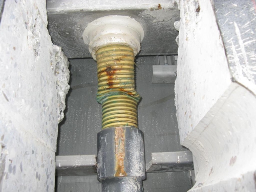
Photo: aqua&pools
Well, of course there are bad examples. The top box to be seen is the overflow channel with a "gutter waste". Right a particularly silly example. The installer should obviously fill in the gaps with planning his means. Particularly interesting is the type of seal with a silicone. Here is a replacement of the entire assembly was required after a few years.
Sometimes it is common, integrating a box in the concrete trough, the one then anbohrt after the tiling at a location, which lies in the grid of tiles.
The channel is the place of the highest pollution of the basin. Is there no other solution, a the no voids, Nesting sites for bacteria, etc deposition of dirt corners. manages? Yes! exact planning!
At the latest at this point an outcry certainly will by all readers, the fight in her pool with loud noises from the trough.
The soft splash water-piping system
No, the issue is not forgotten, but I would like from the other side, approach of the casing forth.
Let us ask ourselves so, what happens in the flood water pipe. There is running water in a pipeline with (hopefully matching) Gradient in direction of the container. As so often in life, the idea is too simple.
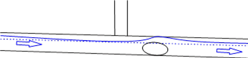
The process is not static but oscillates around the calculated value. Time the wind comes, times a horde of jumping kids in the pool, times is a large sheet on a flow. It is simply a dynamic system, characterized it is in the pipeline regularly to a shaft, which closes the pipe to the air flow.

Wave in the surge water piping, To say: aqua&pools
Just like a traffic jam on the highway, this wave but sometimes does not move with the water but in the opposite direction. Then the shaft drives air in front of you toward pool (Red Arrow) or even to a surge water tank.
Just like the water and the air has to find a way now. If we do not pretend this path through the pipeline, then it will not be the LIGHTEST the way QUIETEST. The best example is the connection of the gravity line from the top to the bus line. I have deliberately chosen terms from the waste piping so that the eyes of every reader open for this specialist field. I think we all agree, NO civil engineers would be a poorly ventilated case-management as the reason- or connect manifold.

Connection flood water from above, To say: aqua&pools
Anyone planning this as, let him please connect his private toilet so!
So far, the considerations were aimed, to push as much water through the channel drain, So we now turn, to take the causes of noisy channel outlets under the microscope. Anyone who has observed such a noisy channel drain, will match, that the noise caused by air.
A stopgap measure against the failure of the tubing in my view, so-called "Flüsterabläufe®". They are to fix a first response to other mistakes of the piping, because they are all too often pushed the pool manufacturer. Instead of correcting the pipelines are "limiter of the flow rate" used. Effectively planned is something else!
As in some programs, it is also the best solution:
The dual computing transition!
Actually, it is not a rake- and no degree program, but the train of thought. Instead of focusing only on the flow of water should worry also the flow of air. Again, we can make use of the experiences of other trades. we put into the treasury of the civil contractors!
Pay attention, Please wake up all PVC pipe fans! We come into the world of eccentric reductions ago! "Channel-ground pipe" is now suitable for our imagination!
The magic words are "flat invert"! Plant one horizontal the inlet to the manifold, then refused to air the way to channel drain. Of course only, when a sufficiently high water line is present in the collection line, otherwise the small lock will not work.
Whoever speculates on the KG-pipes and DN 110 has in mind, Please put in the brain memory and thinking at the end of the article on the effect of the seal!
Correct connection of surge water piping, To say: aqua&pools
The small graph above simplifies the effort something. Instead, many fall lines are, of course, be connected to a collection line. Always the water level has to be right, the volume flow have to be adjusted in line with the dimension. a calculation, better a diligence task. We had already overused formulas Manning's. These are based on practical tests. A bit more sophisticated, and therefore more suitable, I find the more theoretical formulas of Mr. Prandtl and Colebrook. For the purposes of guidance from above I leave that to interested readers, to google this theme.
In the graph of pipelines ellipses are shown. I hope, that is noticed. As with collection lines to common involvement in horizontal angle 45 carried level. The kinetic energy, which has absorbed the water when falling, is brought into the collection line and drives the flow - instead of disturbing them. If the path between the downpipe and connection less than 1 meters is, then the transport capacity of the bus line is increased dependent on the proportion of the volume flow. so do not create reserves by larger sizes, but show confidence (and think about, how the system is changing at full pipeline).
If we have carefully sealed all the channel outlets for the air with the water level, then of course we also need to create ways, on which the air can flow.
Be- and air vent
Thieves- and deaerators are devices, which are only used, if they do not exist. Such as alarm systems ... At least at the end of the bus line is a Be- and air vent may be necessary so that the air escape. Unlike drainage of houses but need not, be done "freedom" in the but can happen in the space of the swimming pool. It makes sense to even, to use the overflow channel. A pipe, which projects into the channel above the water level, In my view, the cheapest solution.
If the amount of Be- and air vent sent into the channel set up, then they can at high loads as an additional channel outlets, so for added security, Act.
Everything has an end, only the sausage has two. Not correct, the pipeline. If need be vented at one end, then of course at the other! Please do not confuse this ventilation with a free fall of the water in the tank! This is an issue in the next article.
Sometimes things get tight ...
... for pipelines. Not always possible to drain with large diameters. Especially when you have to integrate the torrent of water pipes in a finished building, All theory is gray.
Then other solutions must ago. In the next picture may be seen, how difficult the way for pipelines by 1,50 can be meters of reinforced concrete.
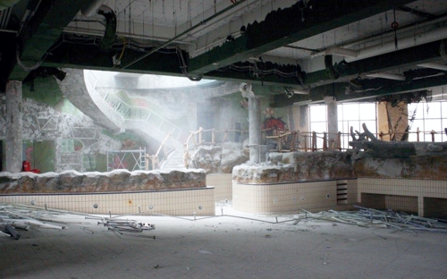
Cored Samoa Warnemünde, Preparation on the way to a-ja, Photo: aqua&pools
Now you can be limited to small diameter and calculate everything in DN50. The client is guaranteed by the grounds for 50 ask holes. Provided one manifold is designed as described above, you can (so to speak, as a small reward) making a further bond with the plumbers and switch to the drainage negative pressure. The filled diameter of the pipe establishes a negative pressure to, which increases the flow velocity in the pipeline to a multiple. In the example shown above pool s are achieved by the difference in height almost 6m /.
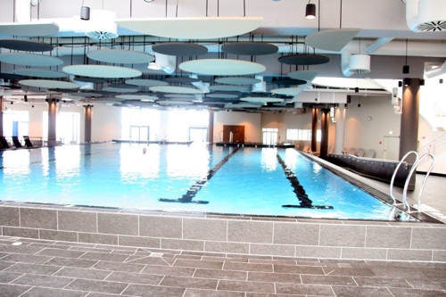
Sports pool at the same point in the a-yes, Photo: aqua&pools
I do not want to destroy at this point the good mood with other formulas. Who needs a table as Excel Help for your own calculation method, please e-mail can log in and ordered as download.
One of the important experiences on the pool construction site, to determine the final position of the channel sequence on the spot and correct if necessary. Then you meet and the slot in the wall. And if someone has once miscalculated: For steel tanks, there are tools and components to also take a sequence later without welding in the gutter to place.
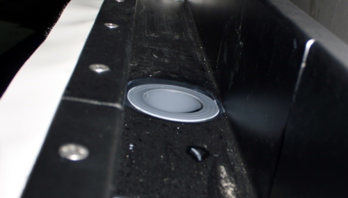
variable channel drain, Photo: aqua&pools
The material question
... is made from time to time for the surge water piping. bring planner, to KG-tubes to exclude, like a so-called KSW approval into play. (KSW: Recommendation of the former Federal Environment Agency on the use of plastics in swimming pool water) Technically, in the KG-pipes most needed fittings (eccentric, 45 city) to find. But these tubes are not intended, to be hung from the ceiling. also, if you have to work with vacuum, then the seals in the KG-fitting are extremely counterproductive. As always: A decision on a case by case.
In the next post we talk about the overflow tank. Thank you for the interest!♦
Print View
If the view is not yet visible, Please wait a few seconds or refresh the page.
Thank you!
 Loading...
For registered members here the print version as PDF:
[wpdm_package id=’1797′]
Leave a Reply
You must be logged in to post a comment.