Published in: Das Schwimmbad und sein Personal, edition 03/2015
Facts about the overflow channel ...
If the theme is to new construction or renovation of a swimming pool, all professionals then agree: The ± 2 millimeters on the overflow edge must be respected!
But the parties agree sufficiently from? In my experience, do not all planners usually, what effects this demand on their work. DIN 19643 referring to the requirements very closely: "The uniform and continuous water overflow must be ensured along the entire length of the overflow channel. The overflow edge must be guided around the entire basin. The edge must lie horizontally on their total length (Deviations do not exceed ± 2 mm).“ Why is this really necessary?
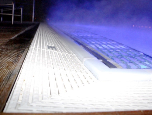
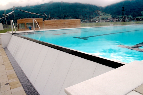
Gutter with ceramic, Photo: aqua&pools
The proportion of dirt, located in or on the water surface, is disproportionately large. A pool with an overflow system is to maintain the surface tension of the water and transporting these contaminants most effective for treatment plant. In my opinion, can the responsibilities of an overflow channel so in 3 summarize parts:
- Function as a weir around the basin,
- Transport of water in the overflow channel in the direction of a channel sequence and
- Feeding the water into the subsequent piping system.
Accuracy of the overflow edge
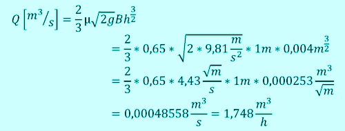
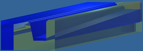
So the overflow edge must be millimeter thus the volume flow (Q) sufficient, to the entire circumference (B) a small difference in height (h) to generate between the water level and the edge. As a check, one can calculate the volume flow, said ± 2 = 4 Millimeter = 0,004 Meters can overcome over a length of 1 meter channel. This is the formula of Poleni as follows:
![]()
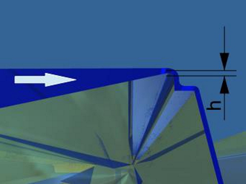
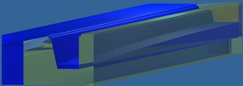
In upper picture it's shown, the stylized channel is transparent and has its own reflections. Now the overflow edge's rounded generally, so that the water can flow smoothly. Therefore, also comes the "discharge coefficient" (µ) in the game. In our case μ ≅ 0,65.
Height h of the overflow edge
Thus the tolerance of ± 2 mm is effective, So must the volume flow in m³ / h greater than 1,75xUmfang the basin in meters be. A rogue, who here think about reality tasks 9. from scool.! But it does not help, we need even deeper into the math.
Kaprun, 1-side curtain of water on stone, 3-each covered gutter, Photo: aqua&pools
Challenges in the planning
The challenge is in the implementation: The further away to this rule a manufacturer feels, the problems are greater, that may arise. On the classic ceramic pool the tiler is responsible for the accuracy, he is usually anchored in treaties by strict guidelines. Knows of the concrete worker, what the tiler needs? Knows the structural engineer, what the concrete workers need? Knows the static engineer, what the structural engineer needs? Knows the ground expert, what the static engineer needs? Knows the horticultural, that he has to deal sensitively with the ground-compressor? It sounds like "Chinese whisper", and it is in practice too often. Regularly is a hole in this virtuell line and when water is poured into the new pool, the dimensions is changing "total surprise". Of course, the Master of pools can ask these questions. That's certainly more effective, than to hope for a happy ending.
There are little things, can abbreviate such guesswork. changed the existing pool when water is poured? The staff on site can give an answer without question. If such a change is suspected, this should be with a precise optical leveler (Pay attention to its accuracy!) be remeasured at the next opportunity and logs.
The experts from the construction are then able, to find the right countermeasures. Experienced companies know this causal line and secure the construction of the pool with reference measurements, often "in the small print".
But what, if the horse has been in the fountain? Then it depends on construction progress and the chosen system. In general, a sample filling to check the tightness is required, that can be used to measure the movements. From these measurements can assbled this pool with a "hump" and so move the filled pool dimensionally back to the required tolerances.
Good experiences I have made, if, to minimize potential interference, set the adjustment of the overflow edge at the end of the construction
can be. Unfortunately, there are also systems, there's a correction is possible only with high construction costs.
Neuruppin, Elevation of the channel on the outside in the field of air bubble bench, Photo: aqua&pools
Nearly philosophical considerations
In the ranks of the pool planners there from my experience is no unity, which philosophy is to be pursued in the planning of the overflow channel: The "Great channel with few drains!"Or the" Small channel with many drains ". Probably stand here the economic considerations of the system provider in the foreground. We do not want to make comparisons between the costs of the gutter and cost of the gutter sequence here, Finally, usually a specialist planners charged with the coordination of trades. Nevertheless, I would like to ask some of the consequences of the choices in the room:
| channel depth | ⇔ | Distance between the channel drains |
| channel depth | ⇔ | Drop height of the water, outgassing, temperature losses |
| channel depth | ⇔ | space requirements |
Some readers will miss the considerations of noise in the processes here. Since these are in my opinion is directly related to the pipes of water gush, I want to consider this issue together to splash water piping.
Here only: Water of the channel has the channel drain! The channel must be large, that it does not overflow.
|
Parts of this series "About the swimming pool technology"
|
Before we talk about this subject, still an experience of "The Practice of simplification". If one wants to be sure, that the channel does not overflow, then you simply select a design, when the overflow edge is a few millimeters lower than the connection to the pool surround. (see photo Neuruppin) Sometimes it can be as simple! The reader may please note my choice of words, because if the sum of the channel outlets is too small, then this trick does not help.
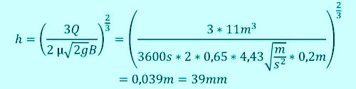
Looking at an even overflow channel, so you can see how in the middle between two sequences is a seamount, the freeboard is there the lowest. Now we add to that vertex mentally a separating wall and at the other end, where the channel drain should sit, we mentally cut the channel from and leave the end open. Finally, we know (still) not, which channel drain dimension is to be carried there. For simplicity, we expect the values of 25×10-meter swimming pool. The circulation capacity is 110m³/h and the scope = gutter length 70m. Our considered one section (Lchannel)should 7 meters feet long, the channel bottom (B) 0,2m wide.

Our well-known from the beginning of the article formula by Poleni we make to h. For μ we must, as it is now at least one open end, initially by a dimensionless value 0,64 accept.

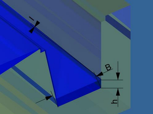
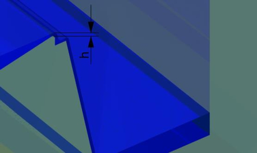
Labeling of the variables at the trough section
In DIN 19643 Notes can be added to surcharges. quote section 9.4: "The overflow channel must also serve the transport and storage. ... In practice, it has a surcharge of 50 % proven to the calculated cross section to compensate for the interference. In addition, the storage space is to be considered (see also DGfdB R 65.06).“
Unfortunately, one finds here no further evidence of the calculation. In my practice has in indoor pool no need for a premium of 50% yield. Heavy loads, by
sudden events, like jumping a group, enter, be delayed as a rule of the overflow and sufficient buffered. The situation is different in wind-influence, which indeed quite often occurs at the outer basin. Here a 50% surcharge to the volume flow was not enough mostly from. Finally, even the wind is able, to move the overflow in one direction and to divert the entire flow to half the length of the channel. Here I give a surcharge of 100% to the volume flow advisable. But beware, it does not arise 100% more groove depth! We will recalculate this later.
a channel, which is to deep, wastes energy and leads to outgassing!
In my view, the majority of errors arising in the area of air attractions, such as underwater loungers. The air, which is pressed here by a compressor, displaces the water 1:1 in the directly adjacent channel. The displacement values can be seen from the performance of the compressor, but beware: The displacement takes place within a few seconds! This flow must [m³/h] be converted.
So it creates a calculation, which is different for certain groove sections.
At the open end of the channel, the water level will be under the terms of 39mm above the channel floor. By calculating, as the water flows in a channel, have been many scholars agonized. We will not go into it here, what distinguishes "flowing" from "gushing" water. We should DIN 19643 follow and is written there, that you follwo to a formula of Mr. Manning, Gauckler and Strickler should. (DIN 19643, point 9.4, equation 12 and 13):
![]()
Where is n flow rate [m/s], ks Value for roughness [1/s], Hydraulic radius R [m], A through-flow cross-section [m²], U wetted perimeter [m], I divide of the water surface (tan a). I allow myself the small correction, is the correct unit to the ks value
![]()
We know the water level on the flat side of the channel drain, but we want to know the water level at the highest point. In between is the gradient, So we put the formula to then:

The individual factors are relatively easy to calculate from the available values.
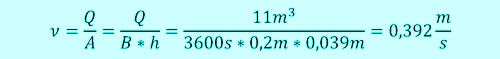
We know, the channel bottom (B) is 0.2m wide by our top Template. The water surface (h) has 0,039m. making it:
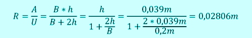
The attentive reader will of course be noticed, that the angle, with which to avoid on your side of the pelvis a free water overflow the overflow channel wall, missing in this formula. Who wants to take into account the angle despite the extremely small changes, this formula should use:

The roughness coefficient ks is dependent on the surface of the chute. In the literature we find information about Sheet Metal gutters and smooth concrete of the order

Channel with linear water level
We assume that, that our channel is smooth and is regularly cleaned. we know the speed of the water well, because what flows over the overflow edge inwards, which must arrive as the sum also at the open end.
So that we can now determine the slope, assumes that the water level in theory:
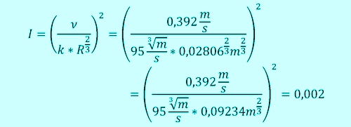
From on high (h), the slope of the water surface (I) can be found and the length of the trough (my interpretation of the DIN 19643) the water level at the other end of the imaginary channel:

Congratulations to all, who have come to this line! But: Here it really starts.
Closer expected to practice
Although the bill already looks very complicated, one can detect deviations to reality.
According to this theory, the water level is a level, in reality it describes a parabola. The formula used by Manning, Gauckler and Strickler describes an open water, enter at the beginning and end same water currents. In our case, the water enters but distributed over the length of the trough. That means, that nothing flows horizontally in the trough at the beginning of the gutter (for there is indeed our imaginary partition).
We could go into the depths of mathematics, but rather stay in a vivid area. At the end of a spreadsheet is we certainly simplify the calculation something.
We share our channel now mentally in 100 individual pieces of equal size and calculate the beginning of each piece separately, respectively with the same calculation process. We have already calculated the start of the zero-piece, it is our place of channel sequence. We know the water level and slope - TO THE NEAREST piece - in 1/100 distance. There, the height of the water level is a little bit (an I L * / 100) higher and the horizontal flow only 99% big. Area and hydraulic radius change, So the results. The gap is partially still low, the overall level always increases less. With these values, we expect some sections, until we have reached the end of the gutter.
Tray with water level in differential calculation
No, no one has to count by hand the one hundred. The function, and the formulas described above with consideration of the inclined wall, you can create in Excel itself.
An email to Dirk.Sura@aquaandpools.de well enough. In response, one can find a small sample calculation and a graph curve. Comments and suggestions on this issue are very welcome! In the next post we talk about channel outlets and the piping to the vessel. Thank you for the interest! ♦
inquiry
Downloads
For downloading the Registierung and or registration is required.
[wpdm_package id=’461′]
The End
 Loading...
Leave a Reply
You must be logged in to post a comment.